Showing posts with label Electronics Circuit. Show all posts

A simple Remote control Tester

March 26, 2010 All in One Blog


Here is a handy gadget for test- ing of infrared (IR) based re- mote control transmitters used for TVs and VCRs etc. The IR signals from a remote control transmitter are sensed by the IR sensor module in the tester and its output at pin 2 goes low. This in turn switches on transistor T1 and causes LED1 to blink. At the same time, the buzzer beeps at the same rate as the incoming signals from the remote control transmitter. The pressing of different buttons on the remote control will result in different pulse rates which would change the rate at which the LED blinks or the buzzer beeps. When no signal is sensed by the sensor module, output pin 2 of the sensor goes high and, as a result, transistor T1 switches off and hence LED1 and buzzer BZ1 go off. This circuit requires 5V regulated power supply which can be obtained from 9V eliminator and connected to the circuit through a jack. Capacitor C1 smoothes DC input while capacitor C2 suppresses any sudden spikes appearing in the input supply. Here, a plastic moulded sensor has been used so that it can easily stick out from a cut in the metal box in which it is housed. It requires less space. Proper grounding of the metal case will ensure that the electromagnetic emissions which are produced by tube-lights and electronic ballasts etc (which lie within the bandwidth of receiver circuit) are effectively grounded and do not interfere with the functioning of the circuit. The proposed layout of the box containing the circuit is shown in the figure. The 9-volt DC supply from the eliminator can be fed into the jack using a banana-type plug.
Tech. Editors note: In fact, the complete gadget can be assembled in the eliminators housing itself and a cut can be made in its body for exposing the IR modules sensor part.
»»  Read more

Free Download Express PCB

March 13, 2010 All in One Blog

The ExpressPCB schematic and PCB design software is very quick to learn and completely free! Download a fully functional version here.

Version: 7.0.2 Date: October 3, 2009 Size: 9.72 Meg


Download Link :
Link 1
( Download Express PCB for XP, 2000 & NT )


Link 2


( Download ExpressPCB for Vista & Windows 7 )
»»  Read more

A Text book of Electrical technology (Volune 2) - B.L Thereja & A.K Thereja

March 12, 2010 All in One Blog

The most important a Ebook "A Text book of Electrical technology (Volune 2) - B.L Thereja & A.K Thereja " for all the Engineering Students .


Every body download this Ebooks

Download Link

»»  Read more

How to Make a LED Flasher Light

March 10, 2010 All in One Blog

It uses a 555 timer ic setup as an astable multivibrator . With the preset at its max. the flashing rate of the LED is about 1/2 a second. It can be increased by increasing the value of the capacitor from 10uF to a higher value. For example if it is increased to 22uF the flashing rate becomes 1 second.

There is also provision to convert it into an alternating flasher. You just have to connect a LED and a 330ohm as shown in Fig.2 to the points X and Y of Fig.1. Then both the LEDs flash alternately.

Since the 555 can supply , you can connect upto about 18 LEDS in parallel both for the flasher and alternating flasher (that makes a total of 36 LEDs for alternating flasher).

Circuit Diagram :


Happy trying...............

»»  Read more

Telephone Ringer using 556 Dual Timers

February 19, 2010 All in One Blog

Using modulated rectangular waves of different time periods, The circuit presented here produces ringing tones similar to those produced by a telephone.
The circuit requires four astable multivibrators for its working. Therefore two 556 ICs are used here. The IC 556 contains two timers (similar to 555 ICs) in a single package. One can also assemble this circuit using four separate 555 ICs. The first multivibrator produces a rectangular waveform with 1-second low duration and 2-second high duration. This waveform is used to control the next multivibrator that produces another rectangular waveform.
A resistor R7 is used at the collector of transistor T2 to prevent capacitor C3 from fully discharging when transistor T2 is conducting. Preset VR1 must be set at such a value that the two ringing tones are heard in one second. The remaining two multivibrators are used to produce ringing tones corresponding to the ringing pulses produced by the preceding multivibrator stages.
When switch S1 is closed, transistor T1 cuts off and thus the first multivibrator starts generating pulses. If this switch is placed in the power supply path, one has to wait for a longer time for the ringing to start after the switch is closed. The circuit used also has a provision for applying a drive voltage to the circuit to start the ringing.
Note that the circuit is not meant for connecting to the telephone lines. Using appropriate drive circuitry at the input (across switch S1) one can use this circuit with intercoms, etc. Since ringing pulses are generated within the circuit, only a constant voltage is to be sent to the called party for ringing.

http://www.electronic-circuits-diagrams.com/telephonesimages/1.gif


Source : electronic-circuits-diagrams
»»  Read more

Electronics Circuit Symbols

All in One Blog

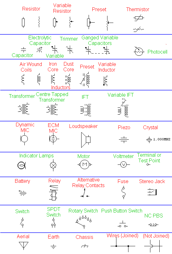
he diagram below shows passive components, resistors, capacitors and inductors, and also electrical components such as switches, relays, motors and lamps. Also shown are the symbols for wires that are not joined ( no physical electrical connection ) and wires that are joined ( a physical electrical connection ).

CIRCUIT SYMBOLS

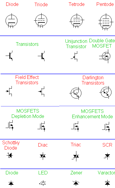
This next diagram depicts active components, the difference between active and passive is that active components require a power source to work, whereas passive components do not. The top symbols represent vacuum tube or thermionic devices. Although at one time, these were being replaced by the smaller transistor and integrated circuits, they are finding their way back into electronics for use in professional audio equipment and some radio receivers

TRANSISTOR COMPONENT SYMBOLS

»»  Read more

Digital Blog ( ডিজিটাল ব্লগ )

Digital Blog on Facebook
Button BEGIN --> Bookmark and Share